


The Dell Optiplex FX160 was announced at the end of 2008. It used the Intel Atom 230 series CPU along with the SiSM671/968/307DV chipset and was available in a number of configurations. What I didn't notice when I first wrote this up was that hardware was sold under two different '160' marketing labels:

The 160 was fitted with a hard disk and sold as small form factor desktop PC running mainstream Windows. The FX160 was sold as a thin client and fitted with a flash drive with Windows XP Embedded as the operating system.
My first purchase was an Optiplex 160, fitted with an 80GB hard drive and had a licence sticker for Windows Vista Home Basic on the bottom. In March 2018 I obtained some FX160s running Windows XPe which has led to the revision of this entry.
As shown above the (FX)160 can also come with a stand so that it can be mounted vertically. The units also carry a model number of DC01T.
The basic specs are:
Processor Type
SpeedIntel Atom 230 single-core processor OR
Intel Atom 330 dual-core processor
1.6GHzMemory 160:
Flash
RAM
FX160
Flash
RAM
0GB/20GB/64GB SSD
or 80GB/160GB 2.5" drive
1GB (Max 4GB)
2GB
2GB (Max 4GB)Video Chip
Max resolution
SiS Mirage 3
VGA: 1920 x 1200
DVI: 1600 x 1200Ports Network
USB
Serial
Parallel
PS/210/100/1000
4 x USB2.0
1
0
Kybd & mousePower Plug
Input
Off
RunningMains IEC connector
100v-240v
1W
16WDimensions W x H x D 269m x 47mm x 252mm (without stand)
The Optiplex 160 came with an internal 80GB 2.5" drive. The licence label on the bottom is for Windows Vista Home Basic edition.
Alternatives would appear to be:
Windows Vista operating system Windows Vista Business SP1 (32 bit)
Windows Vista Home Basic SP1 (32 bit)Windows XP operating system Windows XP Professional SP3 via Windows Vista Business Downgrade Rights (32 bit) Other (may vary by region) FreeDOS (N-series); Novell SUSE Linux Enterprise Desktop 10 (SP2) in China only
Actually somebody had installed Windows 7 Home Premium on this one along the way. The CPU fitted was the Atom 230 along with 2GB of RAM.
The FX160s I got were all fitted with an Atom 230 CPU, 2GB SATA flash Module and 2GB of RAM. They were running Windows XP Embedded.
The FX160 comes with an integral power supply that runs off 100-240V AC.
As noted above my unit is fitted with the Atom 230 CPU. The FX160 Technical Guidebook does say: NOTE: Processor is soldered down on the motherboard.
Linux cpuinfo reports:
CPU family : 6 model : 28 model name : Intel(R) Atom(TM) CPU 230 @ 1.60GHz Stepping : 2 Flags : fpu vme de pse tsc msr pae mce cx8 apic sep mtrr pge mca cmov pat clflush dts acpi mmx fxsr sse sse2 ss ht tm pbe nx lm constant_tsc arch_perfmon pebs bts aperfmperf pni dtes64 monitor ds_cpl tm2 ssse3 cx16 xtpr pdcm movbe lahf_lm dtherm
00:00.0 Host bridge: Silicon Integrated Systems [SiS] 671MX
00:01.0 PCI bridge: Silicon Integrated Systems [SiS] AGP Port (virtual PCI-to-PCI bridge)
00:02.0 ISA bridge: Silicon Integrated Systems [SiS] SiS968 [MuTIOL Media IO] (rev 01)
00:03.0 USB controller: Silicon Integrated Systems [SiS] USB 1.1 Controller (rev 0f)
00:03.1 USB controller: Silicon Integrated Systems [SiS] USB 1.1 Controller (rev 0f)
00:03.3 USB controller: Silicon Integrated Systems [SiS] USB 2.0 Controller
00:05.0 SATA controller: Silicon Integrated Systems [SiS] AHCI IDE Controller (0106) (rev 03)
00:06.0 PCI bridge: Silicon Integrated Systems [SiS] PCI-to-PCI bridge
00:07.0 PCI bridge: Silicon Integrated Systems [SiS] PCI-to-PCI bridge
00:0f.0 Audio device: Silicon Integrated Systems [SiS] Azalia Audio Controller
01:00.0 VGA compatible controller: Silicon Integrated Systems [SiS] 771/671 PCIE VGA Display Adapter (rev 10)
02:00.0 Ethernet controller: Broadcom Corporation NetXtreme BCM5764M Gigabit Ethernet PCIe (rev 10)
This is theoretically straight forward: just undo two screws at the top of the rear panel and then you slide the top forward a short distance and then lift it off. I found that in practice, having removed the screws, the top cover didn't want to move. The answer is to press down on the cover whilst trying to slide it forward. That makes all the difference.

Flash: There are two SATA II connectors on the board. There is an in-line 20-pin power+data connector on the edge of the board (SATA 0), and data connector (SATA 1) mid-board near the heat sinks. To go with the SATA 1 connector there is a separate white 4-pin power connector in the middle of the board labelled SATAPWR1. The hard drive fitted to my unit used the latter connections.
The FX160s had a horizontal DOM plugged into the SATA 0 connector.
I tried out a vertical SATA DOM module that I have in the SATA 0 connector. It's 32mm high. Anything bigger than that is likely to foul the case. Note: If you intend to use this socket there is a BIOS setting that switches this socket ON or OFF.
RAM: The unit accepts one or two DDR2 DIMMs. The sockets are on the edge of the mother board just behind the front panel. Oddly the second socket is angled at 45 degrees. A 2GB Nanya 800MHz part is fitted in my unit. The FX160 Technical Guidebook does say the memory is "DDR2 800MHz" but then goes on NOTE: When 800MHz memory is installed the computer will continue to operate the memory bus at 667MHz. The maximum memory accepted is 2GB per slot.
PCIe: There is an onboard PCIe socket (MINIA1) intended to take a mini PCIe WLAN card.

View of the Optiplex 160 with the hard drive removed. There is a (silent) fan fitted to the bottom of the
bracket that carries the drive. You can see the fan plugs into a socket between the
DVI connector (white) and the serial connector (green).
It's not too clear in the photo, but the white socket near the corner of the top heat sink is the one that provides power to the hard drive.
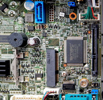
Some more detail on the various connectors.
Top centre the blue data socket for the SATA 1 interface.
On the right the SATA 0 interface.
At the bottom centre the fan connector.
Just above that the PCI-e connector for the WLAN board.
Bottom right, black two-pin connector (below the words SATA) labelled RTCRST. Short to clear the CMOS.
Just below it another two-pin connector (with blue jumper) labelled PSWRST. I'm not too sure what password this resets.
Top right blue jumper (SETUP_LOCK). If in place locks the CMOS settings.
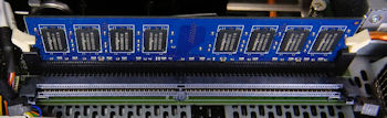
The RAM sockets on the edge of the board.
The unused one is at 45 degrees to the board.