The more modern HP Thin Clients such as the t520, t610 and t620 use the same 19V power supplies as
used by models from their range of laptops. The coaxial connectors on these power supplies actually
have three connections:
The outer barrel - (earth)
The inner barrel - (+19V)
A centre pin - ('smart pin')
The purpose of the centre pin is to signal to the thin client (or laptop) the power rating of the
attached power supply.
If a non-HP (compatible) power supply is used then the HP thin client will not power up. It actually
goes further than this in that a correspondent discovered that his t620 plus would not power up if the
attached HP power supply was rated at less than ~70W.
Some Background
I first met this style of connector many years ago with a DELL laptop where suddenly the laptop
would no longer charge its battery but would still run quite happily off the PSU. It transpired that
the centre pin carried a simple 1-wire serial protocol that let the PSU signal to the laptop the
power rating of the PSU. The laptop then adjusted the battery charge rate to suit the
capability of the charger (eg 65W or 90W). It was this signalling function that had failed in the
charger, and no signalling from the PSU equalled no charging of the laptop battery.
I guess the default of 'no charging' was a marketing decision to persuade customers to buy/use
genuine DELL chargers. The engineering approach would have been to fall back to a safe slow charge rate.
This capability signalling approach has also been adopted by HP but in a different non-compatible way.
(Maybe DELL patented their approach?)
As I write this (July 2021), of thin client manufacturers, I'm only aware of HP and DELL/Wyse that
use this feature in their product range
I guess the HP approach of don't even power up is a marketing (and technical?) decision
to ensure that only genuine HP PSUs are used with their thin clients.
Non HP PSU
If you do an internet search you will find various descriptions of how to get a non-HP power unit
to work with the modern HP thin clients. Essentially it is just a matter of adding a high value
resistor (220k - 330k) between the centre pin and the +19V supply. Originally didn't find any
table that attempted to match PSU power rating to resistor value. All the reports I'd seen were along
the lines: "I soldered in a xxxk resistor and it
worked!".
However in February 2024 I heard from Phillip who had been doing
some experimenting. In May 2024 he followed this up with a more comprehensive list of PSU rating vs
resistor values.
Power
Resistor
230W
100k
150W
121k
120W
182k
90W
294k
65W
383k
45W
500k
Thank you Phillip!
You have two ways of adding the necessary resistor:
Solder the resistor onto the back of the power socket on the thin client.
Solder the resistor into the plug or cable from the PSU.
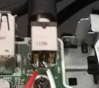
The photo to the right shows the rear view of the power connector fitted to a t620. The resistor has
to connect between the centre pin and either of the 19.5V pins on the back.
In November 2024 I heard from Andrew who commented:
...it appears that some of these USB-C female input to 7.4mm x 5.0mm DC barrel PD cables with a trigger/emulator
PCB for 20v appear to work for powering the HP t630 thin clients from a 65 watt USB-C PSU. Chenyang
has a short cable that gets rebranded by a lot of sellers and is reasonably priced. Search on Amazon for
Chenyang USB C to DC 20V hp 7.4mm or similar.
The short all-in-one adapters
appear not to have the trigger board, it has to be one with the short cable (see photo).
Usage Cases
Various correspondents have their own stories:
In January 2020 I heard from Jeroen who had tried to
use a DELL power supply with his t520.
"I bought the device without a power adapter. Unfortunately, the HP didn't accept a Dell adapter.
But after some research, I found out that soldering a 240k resistor (I only had 480k, so 2 in parallel)
between the center pin and the 19 volts pin does the job."
In May 2021 I had further confirmation from Stuart who
likewise had bought a t520 that had come without a PSU.
"I had a suitably specified laptop power supply but it had the wrong DC connector plug on the end of it.
I ordered the right one (DC Tip 7.4mm x 5.0mm Power Plug Socket connector) off eBay. I cut the old one off
and soldered the new one on - negative to the outer part of the DC plug, positive to the inner part of the
DC plug and ignored the centre pin.
I then tried it out with the t520 - nothing happened, the t520 appeared to be totally dead.
Google then found me further details about the quirks of the HP PSU and also [this parkytowers page]
which said to solder in a 240K resistor on the back of the power input jack. I did this and amazingly it
worked! The t520 powered on.
The photo shows my initial proof-of-concept where I connected the resistor using some flying leads
between the positive and centre pins. I tidied this up once I found it worked."
It is a similar situation with the t620 where I've seen
a recommendation for a 330K resistor
between the centre pin and +19V.
In July 2021 I heard from Thomas who had used a 220k resistor to get his t610 to power up.
In July 2022 I heard from Holger who had experimented with
his t630:
I started with out with a 680k resistor and the t630 ran at 898.2 MHz. Not one MHz more. At the other
end I found that With 220k it would not power up. In the end I used 320k and that worked fine.
A word of caution
As noted above (some? all?) Dell PSUs use a 1-wire serial protocol on the centre pin rather than
using HP's series resistor approach. Connecting this line to +19V albeit through a high value
resistor may or may not damage this feature of a Dell PSU. I have no evidence one way or the other but
do take note if you're also intending to use your Dell PSU with other Dell kit as well as with your HP
thin client. Better still give me a definitive statement on the outcome!
Hacking a DELL power adapter gives more detail of the 1-wire signalling protocol and a guide
to building your own I'm a DELL laptop PSU signaller.
Hacking an HP PSU. In the comments bit there is some useful confirmation:
So I took the failed adapter apart and found the three wire connections on the print board
( + 19v / ground / Smart pin ). I expected some complex circuitry but it was a very simple one.
There was a 200k resistor between the +19v and smart pin connection followed by a small ceramic
capacitor connected to ground. This is for a 90 watt adapter.