


Originally I didn't possess an HP t610 and in Feb 2015 the pictures and information here had kindly been provided by Ken. In July 2017 I got hold of a t610 and updated some of the information on these pages.
Current data sheets on the range of models under the t610 name can be found on HP's website.
"The HP t610 Flexible Thin Clients deliver a true, PC-like experience for virtualized desktop environments. Built using AMD's new APU technology, the HP t610 combines dual core 64-bit processors and AMD HD 6320 graphics. Both thin clients feature DirectX 11 graphics support, DDR3-1600 RAM with up to 8 GB of capacity and AMD A55E Chipset with DVI-I and DisplayPort outputs for exceptional performance."
The t610 is available in a 'fatter' version - the t610 plus - and there is also mention of 'quad head' and 'six head' video options.
The t610 was launched by HP in February 2012.
Processor Type
Speed
ChipsetAMD T56N (dual core)
1.65GHz
AMD A55EMemory Flash
RAM1GB/2GB/16GB
2GB/4GB (16GB Max)Video Chip
Max resolution
Radeon HD 6320
2 x 1920x1200 or
1 x 2560x1600 + 1 x 1920x1200Ports Network
USB
Serial
Parallel
PS/2
Video10/100/1000
4 x USB2.0
2 x USB3.0
1
0
2 (Kybd and Mouse)
DVI-I & DisplayPortPower Power
Plug
Off
Idle
Running19.5V 3A (label)
Coax male 7.4mm/5.0mm + centre pin
1W
~12W
~20WDimensions H x W x D (mm) 240 x 40 x 220 (Excluding Stand) The embedded operating system is one of:
- HP ThinPro
- HP Smart Zero Technology
- Microsoft Windows Embedded Standard 7E
- Microsoft Windows Embedded Standard 7P
- Microsoft Windows Embedded 8 Standard
- Microsoft Windows Embedded Standard 2009
depending on the exact model.

The unit requires a 19.5V supply. The supplied 65W PSU is rated at 19.5V 3.3A. The connector is a male coaxial connector. According to my micrometer the external diameter of the barrel is 7.4mm, the internal diameter 5mm. I don't what the size is of the recessed centre pin.
This style of PSU is also used by a range of HP laptops.
If you don't have an HP PSU/charger and are thinking of using a non-HP PSU see this page.
The CPU fitted to the t610 is from the first generation of AMD's Embedded G-Series System-on-Chip (SOC). It is a dual core CPU clocked at 1.65GHz.
vendor_id : AuthenticAMD cpu family : 20 model : 2 model name : AMD G-T56N Processor stepping : 0 flags : fpu vme de pse tsc msr pae mce cx8 apic sep mtrr pge mca cmov pat pse36 clflush mmx fxsr sse sse2 ht syscall nx mmxext fxsr_opt pdpe1gb rdtscp lm constant_tsc rep_good nonstop_tsc extd_apicid aperfmperf pni monitor ssse3 cx16 popcnt lahf_lm cmp_legacy svm extapic cr8_legacy abm sse4a misalignsse 3dnowprefetch ibs skinit wdt arat hw_pstate npt lbrv svm_lock nrip_save pausefilter vmmcall
00:00.0 Host bridge: Advanced Micro Devices, Inc. [AMD] Family 14h Processor Root Complex
00:01.0 VGA compatible controller: Advanced Micro Devices, Inc. [AMD/ATI] Wrestler [Radeon HD 6320]
00:01.1 Audio device: Advanced Micro Devices, Inc. [AMD/ATI] Wrestler HDMI Audio
00:11.0 SATA controller: Advanced Micro Devices, Inc. [AMD/ATI] SB7x0/SB8x0/SB9x0 SATA Controller [IDE mode] (rev 40)
00:12.0 USB controller: Advanced Micro Devices, Inc. [AMD/ATI] SB7x0/SB8x0/SB9x0 USB OHCI0 Controller
00:12.2 USB controller: Advanced Micro Devices, Inc. [AMD/ATI] SB7x0/SB8x0/SB9x0 USB EHCI Controller
00:14.0 SMBus: Advanced Micro Devices, Inc. [AMD/ATI] SBx00 SMBus Controller (rev 42)
00:14.2 Audio device: Advanced Micro Devices, Inc. [AMD/ATI] SBx00 Azalia (Intel HDA) (rev 40)
00:14.3 ISA bridge: Advanced Micro Devices, Inc. [AMD/ATI] SB7x0/SB8x0/SB9x0 LPC host controller (rev 40)
00:14.4 PCI bridge: Advanced Micro Devices, Inc. [AMD/ATI] SBx00 PCI to PCI Bridge (rev 40)
00:15.0 PCI bridge: Advanced Micro Devices, Inc. [AMD/ATI] SB700/SB800/SB900 PCI to PCI bridge (PCIE port 0)
00:15.2 PCI bridge: Advanced Micro Devices, Inc. [AMD/ATI] SB900 PCI to PCI bridge (PCIE port 2)
00:15.3 PCI bridge: Advanced Micro Devices, Inc. [AMD/ATI] SB900 PCI to PCI bridge (PCIE port 3)
00:18.0 Host bridge: Advanced Micro Devices, Inc. [AMD] Family 12h/14h Processor Function 0 (rev 43)
00:18.1 Host bridge: Advanced Micro Devices, Inc. [AMD] Family 12h/14h Processor Function 1
00:18.2 Host bridge: Advanced Micro Devices, Inc. [AMD] Family 12h/14h Processor Function 2
00:18.3 Host bridge: Advanced Micro Devices, Inc. [AMD] Family 12h/14h Processor Function 3
00:18.4 Host bridge: Advanced Micro Devices, Inc. [AMD] Family 12h/14h Processor Function 4
00:18.5 Host bridge: Advanced Micro Devices, Inc. [AMD] Family 12h/14h Processor Function 6
00:18.6 Host bridge: Advanced Micro Devices, Inc. [AMD] Family 12h/14h Processor Function 5
00:18.7 Host bridge: Advanced Micro Devices, Inc. [AMD] Family 12h/14h Processor Function 7
03:00.0 Ethernet controller: Broadcom Corporation NetLink BCM57781 Gigabit Ethernet PCIe (rev 10)
04:00.0 USB controller: Texas Instruments TUSB73x0 SuperSpeed USB 3.0 xHCI Host Controller (rev 02)
 This is straight forward and requires no tools. First remove the foot if fitted. Then, looking at the
bottom cover of the t610 by the rear panel you will see the words LOCK, PUSH and UNLOCK moulded into
the plastic. Push down on the PUSH tab and slide the cover to the rear and remove it.
This is straight forward and requires no tools. First remove the foot if fitted. Then, looking at the
bottom cover of the t610 by the rear panel you will see the words LOCK, PUSH and UNLOCK moulded into
the plastic. Push down on the PUSH tab and slide the cover to the rear and remove it.
Having done this you can then slide the side cover down about 5mm and then lift it away.
 This reveals the metal screening cover. This has a couple of tabs that are lodged under the edge of the
chassis at the left-hand (backpanel) side and a couple of tab/dimples which are an interference fit
on the right-hand (front panel) side. Put your finger under the tab (arrowed), pull up, and then you
should be able to lift the metal cover clear.
This reveals the metal screening cover. This has a couple of tabs that are lodged under the edge of the
chassis at the left-hand (backpanel) side and a couple of tab/dimples which are an interference fit
on the right-hand (front panel) side. Put your finger under the tab (arrowed), pull up, and then you
should be able to lift the metal cover clear.
When you come to put it back together it is worth checking the tab at the top right (circled). This needs to be inside the internal metalwork, not outside. If it is outside then that corner is slightly proud but not enough to stop a ham-fisted person re-assembling the case and resulting in some small gaps in that corner. (That's the way mine came). It also takes a bit of brute force to get the plastic side cover on risking damage to the lugs on that as well.

Click on the image of the circuit board for a larger version.
Flash: The Flash memory is easily replaceable. It's a DOM plugged into a SATA connector. There is also a standard 44-pin IDE connector (top left-hand corner) and another SATA connector. The detail of the two SATA sockets and the IDE socket are shown below.
In the photograph under the mods tab Ken has fitted a standard 2.5" drive to one of the SATA interfaces.
In September 2024 an email from Arek prompted me to revisit the SATA interfaces on the motherboard. I had assumed that these only supported SSDs and 2.5" hard drives. I thought most? all? thin clients didn't provide 12V power to the SATA connector. It turns out the the t610 does provide +12V power as well as the lower voltages. I connected a Seagate Barracuda 500GB SATA drive to the onboard SATA interfaces in turn and found it was recognised by the BIOS and it proceeded to boot and run the copy of Windows that happened to be on the drive.
Caveat: I do not know what limits may exist to the +12V power that can be drawn by the 3.5" drives.
RAM: The RAM is standard 204-pin DDR3 1600MHz SODIMMs (PC3-12800). The two SODIMMs are on the rear of the motherboard and accessible via a removable panel. (See below). Whilst the t610 is capable of supporting 16GB of RAM, the amount you can actually use will depend on the operating system you have installed (e.g. With 32-bit Windows you don't see much over 3GB). [July 2017: Mario reported he'd successfully installed 16GB of RAM on his t610].
[January 2020] I tried out an 8GB 2Rx8 PC3L-12800S-11-13-F3 part from Hynix HMT41GS6BFR8A-PB which worked.
USB: There are two USB 2.0 ports on the front panel, two USB 2.0 on the rear and two USB 3.0 ports on the rear panel.

The retaining screws to hold the board in place are small. Luckily I found something suitable in my pot of screws from a dismembered laptop. At the time my crude estimate is was ~M1.

Subsequently I heard from Robert who wrote:
"M1.4x3 fits well however with my example I needed to add a home-made washer as the tiny screw head passed through the board mounting hole."
PCI-E: There is what appears to be a PCI-E expansion socket on the edge of the board. This is actually the connector that is used in the t610 Plus variant. The 'plus' version comes in a fatter housing and adds another serial port, parallel port and a half height PCI-E 4x slot. As the expansion socket is used to add a serial and a parallel port as well as a PCI-E 4x slot the connector can't be a standard PCI-E card slot. But all is not lost!
In November 2016 I received an email from Al who was considering using a t610 as the basis of a pfsense router.
"After studying info that I was able to find on the t610 (following traces of the riser card on a picture that I found on google) I came to the conclusion that it seems that the t610 actually has a pcie 4x compatible connector! So... after ordering an extender cable and cutting of the lanes 5-8 I was able to successfully connect a 4 port pcie 4x gigabit card to it."
i.e. The start of the expansion connector exactly matches the pin out of a PCI-E 4x connector. After pin 32 HP must use the remaining pins for the other features of the expansion unit. So, by connecting only those first 32 lines to another PCI-E socket, you can safely plug in and use any standard PCI-E expansion card.
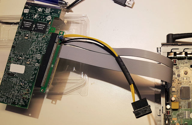
Thank you Al for your detective work and sharing the outcome with us.

Detail of the two SATA ports on the board.

A standard horizontal IDE DOM in place.
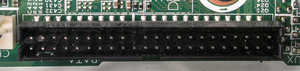
The IDE socket on the board without the DOM in place.
 Note that a standard 44-pin cable connector is wider than the connector on the DOM. If you're using a
cable to connect a hard drive you'll have to remove the plastic from the ends of the IDE socket in order
to be able to plug in a cable.
Note that a standard 44-pin cable connector is wider than the connector on the DOM. If you're using a
cable to connect a hard drive you'll have to remove the plastic from the ends of the IDE socket in order
to be able to plug in a cable.

Access to the RAM located on the bottom of the circuit board.


HP's words for the procedure:
I'm not too sure who wrote this as at step 4 we have: ....nonvolatile memory settings are reset to their factory default values. So why go through steps 5-7 to repeat the process?

However we appear to have an anomaly here. My multimeter clearly shows the power pin sitting at +5V. Kenneth has used this connector to power a couple of fans. He reports:
I did initially try a 5v laptop fan and it blew out at extreme speed in about 3 seconds. The 12v fans I fitted subsequently appear to be operating at full speed.
If you have a t610 please can you let me know whether your t610 has +12V or +5V on this connector.
In November 2021 Robert reported he measured +5V on this pin on his t610 as did another correspondent in December 2021.
In October 2024 I heard from Roland:
Re the Chassis Fan pinning: pin 1 is GND, pin 2 is +5V supply, pin 3 is the "Tacho" measuring the fan speed and pin 4 is the PWM output to the fan for speed regulation.
In practice this connector is used to connect the fan fitted in the Plus version of the t610. If the BIOS detects that the t610 is the Plus version (through the presence of the riser and/or the extra ports it adds?) it will report a "Missing Fan" error at start up and will pause until F1 is pressed.
The fan fitted in the Plus version is a Delta KSB 0405HBF0D which is available without that wonderful housing used in the Plus for about $7. (A replacement from HP comes in around $50!)
Once again my thanks to Ken for the original photographs and information. Ken can be reached
via his website: qrpbuilder.com.