


On the left is a stock photograph of a M100. On the right is the one I have. It is missing its keyboard, two hinge covers and the strip that goes above the keyboard carrying things like the on/off button. However, in compensation, it did only cost me 99p (plus £9 postage). Subsequently I did buy a 'dead' M100 that let me assemble a fully working one from the combined bits.

The M100 carries no manufacturing date. It's part number is DB-A3-KD-BK0.
Processor Type
SpeedVIA Eden
800 MHzChipset VN800 Memory Flash
RAM512MB
512MB (Max 1GB)Video Screen 15" XVGA 1024 x 768 Chip
Max resolutionintegrated in CN800
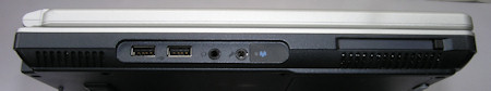
up to 1600 x 1200 32-bit colourPorts Network
USB
Serial
Parallel
PS/210/100
5 x USB2.0
none
none
nonePower Battery 8 cell Li-Ion(4800 mAh) Connector
Charger
Off
RunningCoax 5.5mm/2.5mm
19V/3.42A
0W
~60WDimensions H x W x D (mm) 318 x 277 x 22~36.7
The operating system is Windows XPe.
Mine came without an external power supply/charger. The label on the bottom of the M100 reads "19V 3.42A". The connector is a conventional 5.5mm/2.5mm coax connector .
It is straight forward to get inside the M100 if yours comes with all the bits fitted. Turn it round so you are looking at the back. If you look at the hinge covers you'll see a small slot at the bottom. Using a large flat-bladed screwdriver insert it into the slot and twist gently to overcome the resistance of a couple of clips. Next open the lid fully and you should be able to remove the hinge cover/strip above the keyboard. This lifts from the rear and once free you can lift it clear. After that the keyboard can be moved to reveal the metal shield and the screws necessary to remove that.
For those to whom it matters here is some detail from Linux's /proc/cpuinfo.
vendor_id : CentaurHauls cpu family : 6 model : 10 model name : VIA Esther processor 800MHz stepping : 9 flags : fpu vme de pse tsc msr pae mce cx8 apic sep mtrr pge cmov pat clflush acpi mmx fxsr sse sse2 tm nx pni est tm2 rng rng_en ace ace_en ace2 ace2_en phe phe_en pmm pmm_en
00:00.0 Host bridge: VIA Technologies, Inc. CN700/VN800/P4M800CE/Pro Host Bridge
00:00.1 Host bridge: VIA Technologies, Inc. CN700/VN800/P4M800CE/Pro Host Bridge
00:00.2 Host bridge: VIA Technologies, Inc. CN700/VN800/P4M800CE/Pro Host Bridge
00:00.3 Host bridge: VIA Technologies, Inc. PT890 Host Bridge
00:00.4 Host bridge: VIA Technologies, Inc. CN700/VN800/P4M800CE/Pro Host Bridge
00:00.7 Host bridge: VIA Technologies, Inc. CN700/VN800/P4M800CE/Pro Host Bridge
00:01.0 PCI bridge: VIA Technologies, Inc. VT8237/VX700 PCI Bridge
00:0b.0 CardBus bridge: Texas Instruments PCI1510 PC card Cardbus Controller
00:0c.0 Network controller: Ralink corp. RT2561/RT61 rev B 802.11g
00:0f.0 IDE interface: VIA Technologies, Inc. VT82C586A/B/VT82C686/A/B/VT823x/A/C PIPC Bus Master IDE (rev 06)
00:10.0 USB controller: VIA Technologies, Inc. VT82xxxxx UHCI USB 1.1 Controller (rev 81)
00:10.1 USB controller: VIA Technologies, Inc. VT82xxxxx UHCI USB 1.1 Controller (rev 81)
00:10.2 USB controller: VIA Technologies, Inc. VT82xxxxx UHCI USB 1.1 Controller (rev 81)
00:10.3 USB controller: VIA Technologies, Inc. VT82xxxxx UHCI USB 1.1 Controller (rev 81)
00:10.4 USB controller: VIA Technologies, Inc. USB 2.0 (rev 86)
00:11.0 ISA bridge: VIA Technologies, Inc. VT8237 ISA bridge [KT600/K8T800/K8T890 South]
00:11.5 Multimedia audio controller: VIA Technologies, Inc. VT8233/A/8235/8237 AC97 Audio Controller (rev 60)
00:11.6 Communication controller: VIA Technologies, Inc. AC'97 Modem Controller (rev 80)
00:12.0 Ethernet controller: VIA Technologies, Inc. VT6102 [Rhine-II] (rev 78)
01:00.0 VGA compatible controller: VIA Technologies, Inc.
                                        CN700/P4M800 Pro/P4M800 CE/VN800 Graphics [S3 UniChrome Pro] (rev 01)
 The photo on the right shows the area under the keyboard. Two things of note are the IDE DOM
(bottom right) and the Wireless card (bottom middle).
The photo on the right shows the area under the keyboard. Two things of note are the IDE DOM
(bottom right) and the Wireless card (bottom middle).
 The second IDE interface is a female 44-pin connector that sits at the back of a drive bay that is
revealed if you use a screwdriver to remove a cover on the front of the base of the laptop. The bay is the
right size for a 9.5mm thick 2.5" drive. I inserted an IBM Travelstar 4GB drive with Tinycore 3.0 installed
on it. After a suitable adjustment to the list of boot devices in the BIOS this booted and ran.
The second IDE interface is a female 44-pin connector that sits at the back of a drive bay that is
revealed if you use a screwdriver to remove a cover on the front of the base of the laptop. The bay is the
right size for a 9.5mm thick 2.5" drive. I inserted an IBM Travelstar 4GB drive with Tinycore 3.0 installed
on it. After a suitable adjustment to the list of boot devices in the BIOS this booted and ran.
Ram.
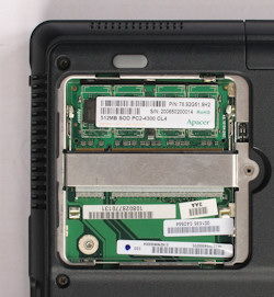 The RAM is located under a panel on the underneath of the laptop. There is space for two SODIMMS to give a
maximum of 1GB of memory. However, in my working example, only a single SODIMM socket is soldered to the
board. In the case of the 'dead' M100, both sockets were in place, so it looks like it may be pot luck as
to how much RAM you can fit.
The RAM is located under a panel on the underneath of the laptop. There is space for two SODIMMS to give a
maximum of 1GB of memory. However, in my working example, only a single SODIMM socket is soldered to the
board. In the case of the 'dead' M100, both sockets were in place, so it looks like it may be pot luck as
to how much RAM you can fit.
The RAM fitted is made by Apacer and marked 512MB SOD PC2-4300 CL4.
Under the keyboard adjacent to the DOM is a mini-PCI socket for a standard wireless modem card. No card was fitted in my M100, but the leads to the aerials were there. I purchased a suitable wireless card from e-Bay for £1.70 and fitted it. (Shown to be a Ralink RT2561/RT61 in the lspci listing).
This is obviously a standard chassis that was designed to carry a CD/DVD drive. To the right of the main circuit board there is a large area of free space that this would have occupied. There is no provision for fitting such a drive and the only access to that space is from the top after the keyboard has been removed. As it is adjacent to the motherboard's IDE connector it would be somewhere to place an IDE-to-CF adaptor should you wish to provide flash storage that way.