The D class is also known as the 5000 range and the D10D is the same as a 5010.
The size of the D class thin client is more in line with the typical sizing of thin clients, and stands some 17cm high compared to the 20cm of the Z class. Correspondingly there is less space inside for those wanting to expand the functionality of their example. A comparison between the two is shown in the photo above. (Note: My D10DP came without a foot).
More details of the D-class range can be found here.

My original example was a D10DP, part # 909648-02, manufactured in October 2013. I subsequently got hold of another one Manufactured in September 2016.
The product labels for each model are shown above and reflect the transition from Wyse branding to Dell. They are both identified as a Dx0D but note the appearance of the 5010 at the end of the PROD ID line in the 2016 one. This later unit still has the WYSE badge across the top at the front, but the moulded name in the plastic side panels has been changed to DELL. As far as I could see the internal circuit board had no obvious revisions.
The basic specs are:
NB:. My D10DP came with a 2GB SATA flash drive. Currently (March 2017) they are being shipped with 8GB SATA flash drives.
Processor Type
SpeedDual core AMD G-T48E
1.4GHzMemory Flash
RAM2GB
2GB (max 8GB)Video Chip
Max resolutionAMD Radeon HD 6250 Graphics
2560 x 1600 32-bit colour (Display Port)
1920 x 1200 32 bit colour (DVI-I port)
1920x1200 32-bit colour (Dual display)Ports Video
Network
USB
Serial
Parallel
PS/21 x DVI-I, 1 x Display Port
10/100/1000
4 x USB2.0
0
0
0Power Plug
Off
Idle
RunningCoax 5.5mm/2.5mm
4 W
14W
16WDimensions H x W x D (mm) 170 x 40 x 185
Operating system: Wyse Thin OS with PCoIP.
For others in the range see the table on the D Class
No power supply came with this so I used a 19V 3.42A Delta Electronics PSU. Note: The 19V rating. If, like me, you have a number of PSUs and thin clients floating around you need to mark this PSU clearly in some way. I'm sure that those which run from 12V - which is most of them - would not take too kindly to 19V. The coax plug is 5.5mm/2.5mm. When I took the power measurements I found this particular PSU seems to take a standing 4W before it is even plugged into the D10DP.
This is fairly straightforward. You need to remove the foot (if fitted) and then the three screws on the back panel. The plastic side cover then slides back a short way can be lifted off. This reveals a metal shield that is dealt with in a similar fashion. This time there are screws in each corner to be removed and a final one in the centre of the edge by the front panel. Once again this panel is slid a short distance towards the rear before it can be lifted clear. (There are three metal lugs each side that locate in small slots in the metal chassis that lock it in place). The speaker is fixed to this panel and will need to be disconnected from the board near to the SODIMM.
For those to whom it matters here is some detail from Linux's /proc/cpuinfo. (Dual Core Processor)
vendor_id : AuthenticAMD cpu family : 20 model : 2 model name : AMD G-T48E Processor stepping : 0 flags : fpu vme de pse tsc msr pae mce cx8 apic sep mtrr pge mca cmov pat pse36 clflush mmx fxsr sse sse2 ht syscall nx mmxext fxsr_opt pdpe1gb rdtscp lm constant_tsc rep_good nonstop_tsc extd_apicid aperfmperf pni monitor ssse3 cx16 popcnt lahf_lm cmp_legacy svm extapic cr8_legacy abm sse4a misalignsse 3dnowprefetch ibs skinit wdt arat hw_pstate npt lbrv svm_lock nrip_save pausefilter vmmcall
00:00.0 Host bridge: Advanced Micro Devices, Inc. [AMD] Family 14h Processor Root Complex
00:01.0 VGA compatible controller: Advanced Micro Devices, Inc. [AMD/ATI] Wrestler [Radeon HD 6250]
00:01.1 Audio device: Advanced Micro Devices, Inc. [AMD/ATI] Wrestler HDMI Audio
00:11.0 SATA controller: Advanced Micro Devices, Inc. [AMD/ATI] SB7x0/SB8x0/SB9x0 SATA Controller [IDE mode] (rev 40)
00:12.0 USB controller: Advanced Micro Devices, Inc. [AMD/ATI] SB7x0/SB8x0/SB9x0 USB OHCI0 Controller
00:12.2 USB controller: Advanced Micro Devices, Inc. [AMD/ATI] SB7x0/SB8x0/SB9x0 USB EHCI Controller
00:13.0 USB controller: Advanced Micro Devices, Inc. [AMD/ATI] SB7x0/SB8x0/SB9x0 USB OHCI0 Controller
00:13.2 USB controller: Advanced Micro Devices, Inc. [AMD/ATI] SB7x0/SB8x0/SB9x0 USB EHCI Controller
00:14.0 SMBus: Advanced Micro Devices, Inc. [AMD/ATI] SBx00 SMBus Controller (rev 42)
00:14.2 Audio device: Advanced Micro Devices, Inc. [AMD/ATI] SBx00 Azalia (Intel HDA) (rev 40)
00:14.3 ISA bridge: Advanced Micro Devices, Inc. [AMD/ATI] SB7x0/SB8x0/SB9x0 LPC host controller (rev 40)
00:14.4 PCI bridge: Advanced Micro Devices, Inc. [AMD/ATI] SBx00 PCI to PCI Bridge (rev 40)
00:14.5 USB controller: Advanced Micro Devices, Inc. [AMD/ATI] SB7x0/SB8x0/SB9x0 USB OHCI2 Controller
00:15.0 PCI bridge: Advanced Micro Devices, Inc. [AMD/ATI] SB700/SB800/SB900 PCI to PCI bridge (PCIE port 0)
00:15.1 PCI bridge: Advanced Micro Devices, Inc. [AMD/ATI] SB700/SB800/SB900 PCI to PCI bridge (PCIE port 1)
00:16.0 USB controller: Advanced Micro Devices, Inc. [AMD/ATI] SB7x0/SB8x0/SB9x0 USB OHCI0 Controller
00:16.2 USB controller: Advanced Micro Devices, Inc. [AMD/ATI] SB7x0/SB8x0/SB9x0 USB EHCI Controller
00:18.0 Host bridge: Advanced Micro Devices, Inc. [AMD] Family 12h/14h Processor Function 0 (rev 43)
00:18.1 Host bridge: Advanced Micro Devices, Inc. [AMD] Family 12h/14h Processor Function 1
00:18.2 Host bridge: Advanced Micro Devices, Inc. [AMD] Family 12h/14h Processor Function 2
00:18.3 Host bridge: Advanced Micro Devices, Inc. [AMD] Family 12h/14h Processor Function 3
00:18.4 Host bridge: Advanced Micro Devices, Inc. [AMD] Family 12h/14h Processor Function 4
00:18.5 Host bridge: Advanced Micro Devices, Inc. [AMD] Family 12h/14h Processor Function 6
00:18.6 Host bridge: Advanced Micro Devices, Inc. [AMD] Family 12h/14h Processor Function 5
00:18.7 Host bridge: Advanced Micro Devices, Inc. [AMD] Family 12h/14h Processor Function 7
04:00.0 Ethernet controller: Realtek Semiconductor Co., Ltd. RTL8111/8168/8411 PCI Express Gigabit Ethernet Controller (rev 06)
It appears to be pot luck as to whether your particular Dx0D has all the 'extra' connectors fitted.
In January 2019 I heard from Andrzej who had a D10D 8GF/2GR, part # 909833-02L, manufactured in July 2015. This did not have the internal mPCIe socket fitted or CN2600 - the internal USB socket.
In June 2022 I heard from Karol. He had recently bought two identical D10D both labelled:
PROD ID: D10D 2GF/2GR INTL
PART NO: 909638-02L
One carried a manufacturing date of April 2015, the other a date of May 2015. The one from April 2015 was NOT fitted with the mPCIe connector, the second SATA port or CN1700. However the one from May 2015 was. Currently I'm not aware of any way of determining exactly what is fitted other than by looking inside.
From what I've seen it looks like the later the manufacturing date the less likely it is to have the sockets fitted. The transition point maybe being mid 2015?
 Click on the photo for a larger version.
The Flash memory in the D10DP is easily replaceable. However the RAM has an obstacle in the way.
Flash: The flash is a small horizontal SATA DOM which can be seen top-middle in the photograph. There are no other SATA sockets on the board.
RAM: The RAM is a 204-pin DDR3 SODIMM can be seen bottom-left in the photograph. The one fitted is a Hynix part: HMT425S6AFR6C-PB NO AA and is labelled 2GB 1Rx16 PC3-12800S-11-12-C3. The maximum RAM capacity is 4GB according to the D-class brochure.
I have since [April 2020] tried out a 4GB Elpida part and an 8GB Crucial part (CT102464BF160B.C16FER). Both of these were correctly reported by the BIOS but I did have issues with Tiny Core Linux. (see the Linux Tab).
The SODIMM socket is located just behind the front panel BUT is tucked under the edge of the circuit board that carries the front panel on/off switch and USB ports. You'll need to take this off if you decide to upgrade the RAM. My later example came without flash or RAM and I found that it was a simple matter of undoing the four securing screws after which you could unplug the daughter board from the motherboard and remove it. Once you've plugged in the new RAM it is a matter of moments to get the daughter board refitted.
mPCIe: There is a mPCIe socket adjacent to the SATA socket. I initially assumed this was for a wireless module but, when I got hold of one with WiFi fitted in May 2017, I found that it was provided by a Wireless card that was wired in to an internal USB port.
I have confirmed that this is a regular mPCIe socket by plugging in an Atheros AR5B91 Wireless card and then a Ralink Rt2790 card. Each appeared on the PCI bus.
Wireless/USB: I subsequently got hold of a D10DP fitted with a Wireless card - reported as a Ralink RT3572. The card, model number WUBR-507N(M)W, was approximately located (with a bit of sticky tape) by the back panel above the DVI connector. It was wired to an internal USB port present on the strip-line connector (CN2600) located between CN4400 and CN7700 (see photos below).
In December 2022 an email from Kris prompted me to take a closer look at this as, having soldered in a strip-line connector to CN2600 on his D10P, he did not gain an internal USB port. Looking closer at my examples I could see that, if the CN2600 connector has not been fitted to the board, then U2600 (a 7534A15) and its associated circuitry has also been left off. U2600 provides the current limited +5V on the USB interface and without it there is no +5V supply present. There maybe other components omitted. If you are interested this page provides some extra detail.
CN1700: This is not fitted in the Dx0D but is fitted in the Dx0Q. It is a 1.25mm JST socket that provides +5V on the two pins closest to the heatsink.
CN4400. A link. In February 2020 I heard from Sandro who had a Dx0D with an unknown password and he was trying to clear the CMOS. He discovered the way to do this was to disconnect the power, move the jumper CN4400 from pins 2-3 to pins 1-2, connect power cord without switching on, wait for about 30 seconds, disconnect the power cord again and move the jumper back to pins 2-3. When you next boot the Dx0D you'll be back with the BIOS defaults.
Subsequently I had a need to reset the BIOS on a Dx0D. For me the sequence: Disconnect the power; briefly move the link across and then back; reconnect the power; worked perfectly.
CMOS Battery. The CMOS battery is located under the circuit board that carries the front panel on/off switch and USB ports.
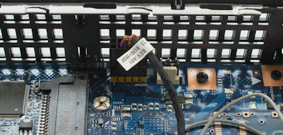
There is another connector on the circuit board that I don't know the purpose of:
CN7700. This socket is on the edge of the board by the SATA socket. It's 5-pin strip but the voltages on it aren't right for a standard USB port.
I haven't taken the motherboard out of the housing, but I did notice whilst peering in through the ventilation slots, a push switch mounted on the rear of the board. Nearby to this is the word 'BIOS'. Once again I have no idea what this switch does.