


The D class is also known as the 5000 range and the Dx0Q is the same as a 5020.
As you would expect there is a great deal of commonality between the Dx0Q and the Dx0D, after all the headline difference is the inclusion of the Quad Core AMD CPU rather than the dual core one of the Dx0D series. However there are other differences and so I thought the 'Q' warranted an entry of its own.
More details of the D-class range can be found here.

My example is a D90Q8, part # 909882-02L, manufactured in May 2016. The label
implies it should have been fitted with a 32GB flash drive and had Windows 8 installed.
The unit came without any flash drive - maybe stripped out and sold separately?
As with most current models this came with the WYSE name on the front panel and the DELL name moulded into the side panels.
The basic specs are:
Processor Type
SpeedQuad core AMD GX-415GA
1.5GHzMemory Flash
RAM32GB
4GB (max 16GB)Video Chip
Max resolutionAMD Radeon HD 8330E Graphics
2560 x 1600 32-bit colour (Display Port)
1920 x 1200 32 bit colour (DVI-I port)
1920x1200 32-bit colour (Dual display)Ports Video
Network
USB
Serial
Parallel
PS/21 x DVI-I, 1 x Display Port
10/100/1000
4 x USB2.0
2 x USB3.0
0
0
0Power Plug
Off
Idle
RunningCoax 5.5mm/2.5mm
0W
7W
9WDimensions H x W x D (mm) 170 x 40 x 185
Operating systems:
Windows Embedded Standard 7
Windows Embedded Standard 8
Windows 10 IoT
No power supply came with this so I used a 19V 3.42A Delta Electronics PSU. Note: The 19V rating. If, like me, you have a number of PSUs and thin clients floating around you need to mark this PSU clearly in some way. I'm sure that those which run from 12V - which is most of them - would not take too kindly to 19V. The coax plug is 5.5mm/2.5mm.
This is fairly straightforward. You need to remove the foot (if fitted) and then the three screws on the back panel. The plastic side cover then slides back a short way can be lifted off. This reveals a metal shield that is dealt with in a similar fashion. This time there are screws in each corner to be removed and a final one in the centre of the edge by the front panel. Once again this panel is slid a short distance towards the rear before it can be lifted clear. (There are three metal lugs each side that locate in small slots in the metal chassis that lock it in place). The speaker is fixed to this panel and will need to be disconnected from the board near to the SODIMM.
The GX-415GA is an AMD 64-bit Quad core CPU clocked at 1.5GHz.
vendor_id : AuthenticAMD cpu family : 22 model : 0 model name : AMD GX-415GA SOC with Radeon(tm) HD Graphics stepping : 1 flags : fpu vme de pse tsc msr pae mce cx8 apic sep mtrr pge mca cmov pat pse36 clflush mmx fxsr sse sse2 ht syscall nx mmxext fxsr_opt pdpe1gb rdtscp lm constant_tsc rep_good nonstop_tsc cpuid extd_apicid aperfmperf pni pclmulqdq monitor ssse3 cx16 sse4_1 sse4_2 movbe popcnt aes xsave avx f16c lahf_lm cmp_legacy svm extapic cr8_legacy abm sse4a misalignsse 3dnowprefetch osvw ibs skinit wdt topoext perfctr_nb bpext perfctr_llc hw_pstate proc_feedback vmmcall bmi1 xsaveopt arat npt lbrv svm_lock nrip_save tsc_scale flushbyasid decodeassists pausefilter pfthreshold overflow_recov
00:00.0 Host bridge: Advanced Micro Devices, Inc. [AMD] Family 16h Processor Root Complex
00:01.0 VGA compatible controller: Advanced Micro Devices, Inc. [AMD/ATI] Kabini [Radeon HD 8330E]
00:01.1 Audio device: Advanced Micro Devices, Inc. [AMD/ATI] Kabini HDMI/DP Audio
00:02.0 Host bridge: Advanced Micro Devices, Inc. [AMD] Family 16h Processor Function 0
00:02.3 PCI bridge: Advanced Micro Devices, Inc. [AMD] Family 16h Processor Functions 5:1
00:10.0 USB controller: Advanced Micro Devices, Inc. [AMD] FCH USB XHCI Controller (rev 01)
00:11.0 SATA controller: Advanced Micro Devices, Inc. [AMD] FCH SATA Controller [AHCI mode] (rev 40)
00:12.0 USB controller: Advanced Micro Devices, Inc. [AMD] FCH USB OHCI Controller (rev 39)
00:12.2 USB controller: Advanced Micro Devices, Inc. [AMD] FCH USB EHCI Controller (rev 39)
00:13.0 USB controller: Advanced Micro Devices, Inc. [AMD] FCH USB OHCI Controller (rev 39)
00:13.2 USB controller: Advanced Micro Devices, Inc. [AMD] FCH USB EHCI Controller (rev 39)
00:14.0 SMBus: Advanced Micro Devices, Inc. [AMD] FCH SMBus Controller (rev 3a)
00:14.2 Audio device: Advanced Micro Devices, Inc. [AMD] FCH Azalia Controller (rev 02)
00:14.3 ISA bridge: Advanced Micro Devices, Inc. [AMD] FCH LPC Bridge (rev 11)
00:18.0 Host bridge: Advanced Micro Devices, Inc. [AMD] Family 16h Processor Function 0
00:18.1 Host bridge: Advanced Micro Devices, Inc. [AMD] Family 16h Processor Function 1
00:18.2 Host bridge: Advanced Micro Devices, Inc. [AMD] Family 16h Processor Function 2
00:18.3 Host bridge: Advanced Micro Devices, Inc. [AMD] Family 16h Processor Function 3
00:18.4 Host bridge: Advanced Micro Devices, Inc. [AMD] Family 16h Processor Function 4
00:18.5 Host bridge: Advanced Micro Devices, Inc. [AMD] Family 16h Processor Function 5
01:00.0 Ethernet controller: Realtek Semiconductor Co., Ltd. RTL8111/8168/8411 PCI Express Gigabit Ethernet Controller (rev 06)
 Click on the photo for a larger version.
Flash: The flash is a small horizontal SATA DOM (missing in my case). There is also a separate SATA data connector on the board.
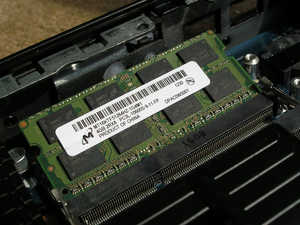
RAM: The RAM is a 204-pin DDR3L SODIMM can be seen bottom-left in the photograph. The one fitted is a Hynix part: HMT451S6BFR8C-PB NO AA and is labelled 4GB 1Rx8 PC3-12800S-11-13-B4. There are two RAM sockets, one above the other.
I have since [April 2020] tried out an 8GB Crucial part (CT102464BF160B.C16FER). This worked.
The SODIMM sockets are more accessible than on the Dx0D range as the front panel board has been redesigned so that it no longer overhangs the SODIMM. I do have a Dx0D of a later manufacturing date (September 2016) which is the same as the earlier examples I had which implies that this change is unique to the 'Q' version.
In May 2020 I came to press a Dx0Q into service and decided to upgrade it to use 2 x 4GB SO-DIMMs. It was then that I discovered that, whilst the top socket was simple to use, the bottom socket was a completely different story.
Firstly, as with the Dx0D, you have to remove the small daughter board to be able to get at the socket.
 Next, having seated the RAM in the socket, I found that when I tried to push it down to the
horizontal to latch it in place, the top edge fouled the two white translucent
bits of plastic on the back of the front panel. In the photo the one on the left is the
'plunger' on the back of the power push button that engages with the switch on the (removed)
daughter board. The one on the right is a 'light pipe' from the disk activity LED (on the
removed daughter board) to the front panel.
Next, having seated the RAM in the socket, I found that when I tried to push it down to the
horizontal to latch it in place, the top edge fouled the two white translucent
bits of plastic on the back of the front panel. In the photo the one on the left is the
'plunger' on the back of the power push button that engages with the switch on the (removed)
daughter board. The one on the right is a 'light pipe' from the disk activity LED (on the
removed daughter board) to the front panel.
With a touch of brute force and judicious levering with a screwdriver, I managed to get it past the obstructions and seated properly in its socket.
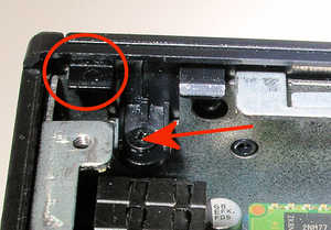 Subsequently a few correspondents pointed out the solution was to undo two screws and remove
the front panel to which the offending plastic bits are fixed. The photo shows one end of the
front panel with the arrow indicating the fixing screw. Circled is a black plastic tab that clips
over a bit of metal work. As well as the ones each end of the panel there is also one of these
in the middle. These have to be 'unclipped' in order to remove the panel.
Subsequently a few correspondents pointed out the solution was to undo two screws and remove
the front panel to which the offending plastic bits are fixed. The photo shows one end of the
front panel with the arrow indicating the fixing screw. Circled is a black plastic tab that clips
over a bit of metal work. As well as the ones each end of the panel there is also one of these
in the middle. These have to be 'unclipped' in order to remove the panel.
mPCIe: There is a mPCIe socket adjacent to the SATA socket.
TPM:The specification mentions a Trusted Platform Module (TPM). In my case I don't think this is fitted - possibly removed by the vendor? Tiny core Linux doesn't find it but maybe the TPM support modules aren't in the distribution? (Neither does Fedora 28 Workstation find it). As you can see above the label on the unit does read: D90Q8 15W TPM 32GMF/4GR ES INTL which implies one might have been fitted originally.
There are a few other connectors dotted around the circuit board most of which I don't know the purpose of.
The double-banked RAM sockets.

Along the bottom edge of the circuit board we have:

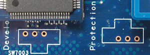
CN4400. A Link. It has 'Protection' silk-screened by it. I assume this functions the same way as the CN4400 link on the Dx0D and can be used to reset the CMOS.
CN2600 that looks like a connector for two more USB ports. It is marked 'Developer'.
CN5 which is a ZIF connector - similar to the keyboard connector on some laptops.
Checking the Dx0D board (where the sockets aren't fitted) we can see the 'Protection' link and can see that the 'Developer' connector only has three lines connected. (Data in/out and ground of a serial debug port?).
Near the power connector we have:
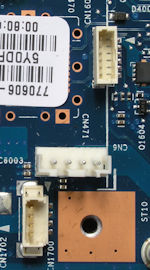
CN1700 a small 4-pin 1.25mm JST socket. I measure +5V on the two pins closest to the heatsink. Ammon confirmed that it was just the thing for powering another SATA drive. (See the Using tab).
CN6 4-pin JST socket - I measure +12V on the two pins closest to the front panel. Could be power for a fan?
CN1601 6-pin socket.
Near the SATA Data socket and CPU heatsink:
 CN3 Dual row of small pins (2 x 15).
In March 2020 I heard from Jacob who had recently got a Dell Zx0Q whose motherboard layout was quite similar to the one in the Dx0Q. That particular model was fitted with an expansion board with two serial connectors and a parallel connector. This daughterboard was plugged into CN3. One might assume that CN3 on the Dx0Q motherboard has similar functionality - but the Dx0Q case does not have the space for much in the way of additional connectors.
As with the Dx0D I haven't taken the motherboard out of the housing, but I did notice whilst peering in through the ventilation slots, a push switch mounted on the rear of the board. Whilst on the Dx0D nearby to this is the word 'BIOS' on the Dx0Q board it is marked with a more anonymous label of 'SW7004'.