
Improving the cooling on an Asus VivoBook S200E/X202E/Q200E

Background
I've had an Asus S200E for many years which has had light use over that time. I've always noticed that the cooling fan seems to be running all of the time and some time ago thought that I should take a look at things, see what was going on and see if I could improve matters.
In August 2018 I bought another S200E off eBay at a bargain price. The reason that it was a bargain was that the vendor described it as "sluggish" and hazarded a guess that the hard drive was on the way out. My guess was that this was just a cooling/throttling issue and seemed to me to be the ideal candidate for some exploratory work. (My guess was correct).
A few minutes with Google showed that the basic cooling design for this model (and its variants) appeared to be marginal at best and many people had problems with high CPU temperatures and the CPU more often than not being throttled back to let things cool down. There were various suggestions on how this could be dealt with ranging from "Clean the fan" through radical surgery to "Bin it".
I decided to take a step-by-step approach and see how things improved along the way.
Disassembly
To do anything other than the most superficial of solutions you are going to have to take the S200E apart. There are plenty of YouTube videos which show you how to do this so I won't duplicate things here - check them out.
Essentially it is just a simple matter of undoing 9 screws and carefully/gently removing the bottom of the laptop. Do note which screws come from where as the lengths of the screws do vary (front/middle/back).
Cooling System
Before we progress further it is worth looking at how the Asus S200E cools the CPU.
Once you have the bottom off the S200E you can see the cooling fan and the black metalwork that extends out to cover the CPU and the RAM.
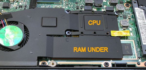
Two things immediately stand out and you'll discover a third later:
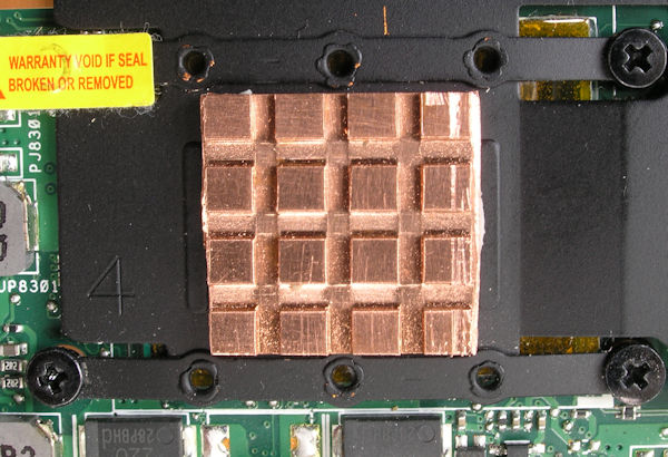
- The heatsink (if you can call it that) is formed out of a single sheet of thin copper. There are no fins on it or anything to facilitate the transfer of heat from the copper sheet to the air flowing over the top of it other than black paint.
- There is very little vertical space. The fan/heatsink is fitted into a gap of ~6.5mm between the motherboard and the bottom cover.
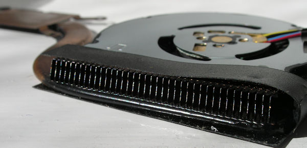
- When you remove the fan you will find that the fan just blows the air out through a rectangular vent. There are no 'fins' across the vent to assist in heat transfer from the copper.
All in all it isn't surprising that the cooling is a little bit wanting.
Looking in a little more detail:

The fan is a centrifugal fan which draws air in from the top of the fan and blows it out the back of the laptop - actually straight at the hinge. The centre of the fan is stepped up by ~1mm and there is the small bump formed into the metal of the heatsink between the fan and the CPU. I assume the 'bump' and the centre of the fan rest against the bottom of the case in which case the exhaust air is being drawn into the fan through a gap of around 1mm between the fan and the bottom cover.
If we superimpose the grill area of the bottom cover over the heatsink we can see the possible airflow.

So the heat from the CPU is transferred to a sheet of copper and from thence to the air flowing over its upper surface. (Upper as we look at the photo). The air is then expelled through the grille at the back of the laptop just in front of the screen hinge.
As things go it's not very good:
- There are no fins anywhere to increase the surface area and aid the heat transfer from the metal to the air.
- Heat is transferred away from the CPU through the thin copper of the flat heat sink - something that has a small cross-sectional area and cannot be particularly efficient at shifting it.
Internet solutions
On searching the Internet I found a number of solutions where the authors had stacked several thermally conductive pads on top of the heatsink. These actually block the airflow but use the bottom of the laptop as a large (plastic!) heatsink. I wasn't interested in doing this and so set off down a different path.
The starting point
My eBay bargain had a freshly installed copy of Windows 10. To this I added HWMonitor from CPUID to monitor the CPU temperatures and the Intel Extreme Tuning Utility that could let me load up the CPU.
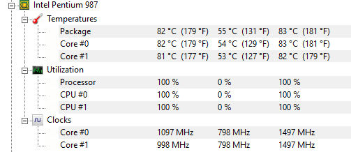
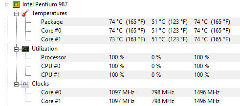
Before starting on any modifications I fired up the laptop and measured the CPU temperatures:

As you can see the CPU temperature has hit 90°C. This S200E was fitted with a Pentium 987 CPU which is specified for a maximum junction temperature of 100°C.
Just a comment on Clocks. I assumed that these would move towards the headline figure of 1.5GHz as I made the various improvements, after all that's what is on the specification sheet. They didn't. I'll come back to that at the end. The steps below are just concentrating on the CPU temperatures.
Step 1
High in the solutions list: "Clean the fan" (obvious!) and "the thermal paste has dried out, replace it". I did both at the same time, but I believe all the improvement came from the "clean", the re-pasting added nothing. The 'clean' involved blowing/brushing out all the dust from the fan and the various vents on the laptop.
Ok, we've now got the temperature down to 83°. A step in the right direction, but that hasn't got us very far.
Step 2
In searching around I'd come across a thin copper heatsink 2mm high intended for M.2 style SSDs. (eBay "Copper Heatsink Thermal Conductive Adhesive For M.2 NGFF 2280 PCI-E NVME SSD 2mm" from Hong Kong, ~2UKP delivered).
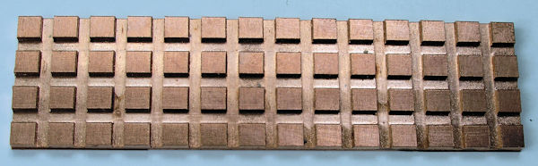
I purchased one, cut out a three-by-three section which I fitted (using a thin thermal pad) in the depression directly over the CPU.
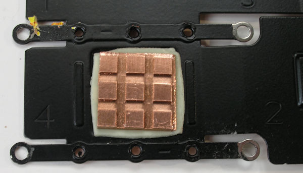
This should facilitate the transfer of heat from the CPU to the air being drawn across it by the fan.
Ok, we've now got the temperature down a further 9°C to under 75°C. Looking good.
One possibility to get the temperature down further might be to add some more 'finnage' elsewhere on the heatsink.
I subsequently noticed that the thermal pad was just a little thicker than the depression in the heat sink. This meant the added copper heatsink could actually be slightly larger at 4x4 - which would have saved me a little work with the hacksaw.
Another thought was to cut out a suitable square hole so that the copper finned heat sink could be mounted directly on the CPU rather than having a paste/copper/thermal pad path between them - but I had something else lined up.
Step 3
At this point I changed track. I was interested in the effect of the first two steps but in my search for a solution I had come across an alternative heatsink for the S200E (part number 13NB00L1AP0501). This used a heatpipe to conduct the heat away from the CPU to a grille across the exhaust port of the fan.

This looked a far better solution for cooling the CPU. I do not know if this is a standard Asus part. There may have been a change to the design at one point? All I knew was that it was advertised as fitting the S200E.
At the time of writing a number of suppliers in the USA stocked these - but with postal charges to the UK being about 1.5x the cost of the item. (~$12 + $18). However I did track down some on AliExpress and ordered from there for ~10UKP delivered, but with a wait of a few weeks whilst they made their way to the UK from the Far East.
The new fan is a drop-in replacement for the old one, but you have to remove one additional screw from the board to fix it in place. (The one by the white arrow head in the photo at about 2 O'Clock position on the fan).

With it in place we have a healthy reduction in the CPU temperature.

At this point I stopped. The alternative fan/heatsink was the ideal solution and at 10UKP not particularly expensive.
Clock Rate
I don't profess to know exactly what is going on with the CPU clock rates. All I know is that the Pentium 987 has two cores, a Processor Base Frequency of 1.50GHz, a max junction temperature of 100°C and a TDP of 17W. It does not support Intel Turbo Boost Technology.
When I ran the CPU stress test the CPU clock rate always settled around 1GHz, not the 1.5GHz that I expected.
Breaking out sections of the display from the Intel Extreme Tuning Utility when it is running the CPU stress test we can see:
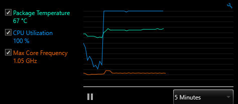
This shows the graphs for the package temperature, CPU utilisation and core frequency. As you'd expect, the CPU utilisation jumps to 100% at the start of the test and the package temperature increases. However, after an initial spike in the CPU frequency, it ticks along around 1GHz.

The two things of interest on this screen are at the bottom. It is reporting that there is no thermal throttling and that the current package TDP is 8W.

Finally, from the top right of the display we have the above.
To me this implies that the CPU is being run with a maximum TDP of 8W but will allow occasional excursions to 17W. Where we have a prolonged activity - such as the CPU Stress Test that was in progress, the clocks are adjusted so that the TDP is just 8W.
Where this is set I have no idea. Was it a consequence of my running the utility? Is it embedded somewhere in the Windows 10 power profiles? Is it necessary?
A mystery that remains to be solved.