


There is no indication of the date of manufacture. At the time of writing (May 2016) Netvoyager's website shows this as a current product. However VIA's website shows the CN896 Northbridge chip used in this product as being 'EOL'. I think LX-1022 might have been released around 2010.
Once I took it apart I found that the hardware is made by Astec.
Processor Type
SpeedVIA Eden
1GHzMemory Flash
RAM512MB
512MB (Max 2GB)Video Chip
Max resolutionCN896
1920 x 1200 24-bit colourPorts Network
USB
Serial
Parallel
PS/210/100/1000
4 x USB2.0
0
0
2 (Kybd & Mouse)Power Power
Connector
Off
Running12V 3A (label)
Coax 5.5mm/2.1mm
1 W
14WDimensions H x W x D (mm) 209 x 150 x 39.8 The embedded operating system is the "Netvoyager Phoenix Operating System".
For those to whom it matters here is some detail on the CPU:
vendor_id : CentaurHauls cpu family : 6 model : 13 model name : VIA Eden Processor 1000MHz stepping : 0 flags : fpu vme de pse tsc msr pae mce cx8 apic sep mtrr pge cmov
pat clflush acpi mmx fxsr sse sse2 tm nx up pni est tm2 xtpr
rng rng_en ace ace_en ace2 ace2_en phe phe_en pmm pmm_en
00:00.0 Host bridge: VIA Technologies, Inc. CN896/VN896/P4M900 Host Bridge
00:00.1 Host bridge: VIA Technologies, Inc. CN896/VN896/P4M900 Host Bridge
00:00.2 Host bridge: VIA Technologies, Inc. CN896/VN896/P4M900 Host Bridge
00:00.3 Host bridge: VIA Technologies, Inc. CN896/VN896/P4M900 Host Bridge
00:00.4 Host bridge: VIA Technologies, Inc. CN896/VN896/P4M900 Host Bridge
00:00.5 PIC: VIA Technologies, Inc. CN896/VN896/P4M900 I/O APIC Interrupt Controller
00:00.6 Host bridge: VIA Technologies, Inc. CN896/VN896/P4M900 Security Device
00:00.7 Host bridge: VIA Technologies, Inc. CN896/VN896/P4M900 Host Bridge
00:01.0 PCI bridge: VIA Technologies, Inc. VT8237/VX700 PCI Bridge
00:02.0 PCI bridge: VIA Technologies, Inc. CN896/VN896/P4M900 PCI to PCI Bridge Controller (rev 80)
00:03.0 PCI bridge: VIA Technologies, Inc. CN896/VN896/P4M900 PCI to PCI Bridge Controller (rev 80)
00:0f.0 IDE interface: VIA Technologies, Inc. Device 5372
00:0f.1 IDE interface: VIA Technologies, Inc. VT82C586A/B/VT82C686/A/B/VT823x/A/C PIPC Bus Master IDE (rev 07)
00:10.0 USB Controller: VIA Technologies, Inc. VT82xxxxx UHCI USB 1.1 Controller (rev b0)
00:10.1 USB Controller: VIA Technologies, Inc. VT82xxxxx UHCI USB 1.1 Controller (rev b0)
00:10.2 USB Controller: VIA Technologies, Inc. VT82xxxxx UHCI USB 1.1 Controller (rev b0)
00:10.3 USB Controller: VIA Technologies, Inc. VT82xxxxx UHCI USB 1.1 Controller (rev b0)
00:10.4 USB Controller: VIA Technologies, Inc. USB 2.0 (rev 90)
00:11.0 ISA bridge: VIA Technologies, Inc. VT8237S PCI to ISA Bridge
00:11.7 Host bridge: VIA Technologies, Inc. VT8251 Ultra VLINK Controller
00:13.0 Host bridge: VIA Technologies, Inc. VT8237A Host Bridge
00:13.1 PCI bridge: VIA Technologies, Inc. VT8237A PCI to PCI Bridge
01:00.0 VGA compatible controller: VIA Technologies, Inc. CN896/VN896/P4M900 [Chrome 9 HC] (rev 01)
04:04.0 Ethernet controller: Realtek Semiconductor Co., Ltd. RTL-8110SC/8169SC Gigabit Ethernet (rev 10)
80:01.0 Audio device: VIA Technologies, Inc. VT1708/A [Azalia HDAC] (VIA High Definition Audio Controller) (rev 10)

The unit requires a 12V supply with a coax 5.5mm/2.1mm plug. Something that supplies at least 2A should suffice.
Click on the photo for more detailed pictures of the circuit board.
As far as expanding the memory it's just a matter of undoing one screw and removing the side panel of the LX-1022:
Flash. The flash memory is a 512MB Compact Flash Card. You can obviously replace this by larger capacity cards.
RAM The RAM is a standard DDR2 SODIMM. The one fitted is made by TLA and is marked 512MB 200PIN DDR2667. The part number is AD2SHH12S5WB-6EgE. The datasheet describes the RAM as a '512MB DDR-2 RAM @ 677Mhz'.
I haven't checked to see what the largest size supported is. However VIA's datasheet on the CN896 does say under 'System Memory':
and elsewhere:
...which implies a 2GB DIMM should work.

PCI There is a mini PCI express slot also available.
If you take the case apart you'll find some other connectors on the other side of the circuit board.

Power There is a two pin connector adjacent to the power socket.

Fans There are two points (only one fitted with a connector) for connecting a fan.
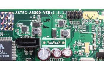
Sata Socket The board is tracked for two SATA sockets but only one
is fitted. (I'm uncertain what J1 is for)
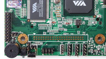
IDE & USB There are a number of connectors grouped in the corner of the board.
Bottom right there are connectors for four USB ports.
The IDE connector is not fitted