

It's not the simplest of jobs to get into the TC190, it takes a little time....
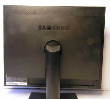
Looking at the back of the TC190 the first step is to remove the push-fit back cover that is covering up the screen mount. I found that it was relatively easy to remove by hand without the need for any levering tool.
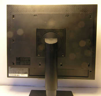
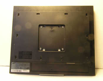
With that out of the way you can undo two screws and remove the screen mount.
The next step is to remove the plastic back. This extends out to the screen bezel. It's a matter of taking your time and being gentle. I found a convenient point to start was in the middle at the bottom where the switches are. From there work left and right...
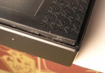
This is when I reached the right corner. I had been using a small flat bladed screwdriver which you can see has marked the plastic slightly.
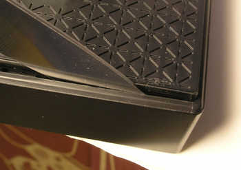
I then switched to using a thin blade which was better. Here I'm using a knife I 'borrowed' from the knife drawer in the kitchen.
There are actually four tabs on each edge of the screen bezel. These are locating in indentations on the side of the panel you are removing. As you lever away to part the two you can raise the back a fraction which stops them popping back as you work along the edge.
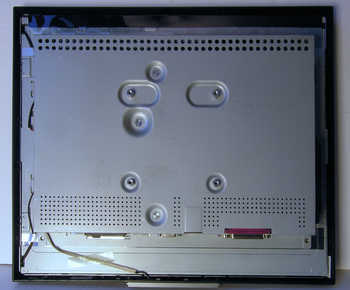
With the back out of the way you reveal the metal shield that encases the various circuit boards.
This is not actually fixed in place with any screws but I guess is held in place by the panel we've just removed.
Next it is a matter of disconnecting various connectors so we can lift it away from the screen.
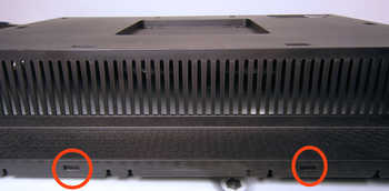
There are three connectors at the left-hand side (looking from the rear)...
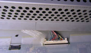
...and one on the top edge which is the screen connector. For this one, if you look closely, you will see there are some small metal levers each side. Press these towards the middle and the connector should come away easily.
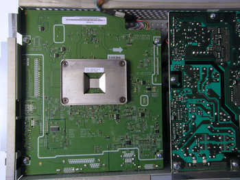
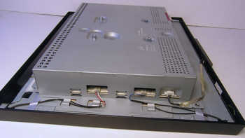
We now have the guts of it separated from the screen and turning it over we can see the bottom of the thin client circuit board and the power supply circuit board. There are four screws holding the thin client circuit board in place. Undo these.
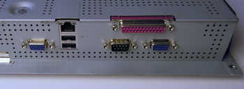
Before the board can be removed we also need to remove the eight pillars clamping the Video/Serial/Parallel port connectors to the metalwork.
Having undone these the board can be removed, but you all also have to remove the plastic cover for the audio/usb connectors on the right hand side. (It comes away easily)
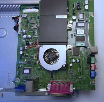
Having flipped the board over you can get at the power connectors - top left in the photograph. With them disconnected you have got the board clear of everything and you can now change the flash and/or RAM at your leisure.
Having been through the hassle of taking it apart the first thing I did was replace the CMOS battery. (It was dead anyway, but as they aren't expensive I would suggest that you automatically replace it if you don't know its history as it takes a fair amount of effort to get to it).
That's it. As always just reverse the process to put it back together.