I finally found a tool to change the CPU clock multiplier in the
t5520, specifically this one:
https://www.vogons.org/viewtopic.php?f=46&t=74359 (version 2.2 worked
for me in Windows 98 SE, I didn't try other versions)
The t5520 uses an FSB speed of 133MHz, so the default multiplier is 6
in order to get a clock speed of about 800MHz. Using that tool, I was
able to raise the multiplier to 8 (about 1066MHz), at which point my
unit was still stable. At a multiplier of 8.5 (about 1133MHz) my unit
was no longer completely stable, but was still able to run a few
benchmarks and tests at that speed.
Later, I was reading documentation regarding other CPUs using the same
VIA Nehemiah core, and found that despite the Eden ESP8000 in the
t5520 using a VCore voltage of 1.05V, there were faster bins of the
same chip being sold with C3 branding, using voltages of 1.25V or even
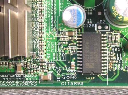
1.45V. Some investigation of the various ICs inside the unit led me to
the regulator supplying VCore, which in my unit is a Semtech SC1189SW
located at U7. When the unit is standing upright in the stand, it's
the bottom-most IC visible, near the CPU heatsink.
According to the datasheet, assuming the
VID25MV pin is low (in the
t5520, it is), the stock setting of 1.05V is obtained by setting
VID[3:0] to 0100. For 1.25V, this would need to be changed to 0000, or
in other words VID2 needs to be changed from high to low. VID2 is
located at pin 19 of this IC. This IC has internal pull up resistors,
so at least in my unit, HP set this pin high by simply not connecting
it to anything. This means that connecting it to ground will pull it
low. Conveniently, the two adjacent pins (pin 18/VID3 and pin 20/VID1)
are both already connected to ground, so all that is needed is to
connect pin 19 to either of the two adjacent pins. I did so, powered
the unit on, and confirmed that VCore was now reported as 1.25V
instead of the original 1.05V.
With the higher voltage, the CPU did become noticeably warmer (a fan
would be needed for prolonged operation), but some quick
experimentation showed that I was now able to reach a clock speed of
about 1466MHz (multiplier setting of 11), which is 83% faster than
stock. I have not yet tested if this speed is stable.
Seeing as how some of the higher-end CPUs using the same core run at
1.45V, it may be possible to get even more speed by using that voltage
- this would involve disconnecting pin 18 from the board and leaving
pin 19 alone. I have not tried this yet, but I may install some
switches on mine so I can easily switch between 1.05/1.25/1.45V (or
even 1.65V by grounding pin 19 but not 18 - but I'd be worried about
CPU damage with voltage that high). I think the power devices in the
VCore supply circuit can handle the increased power demands, but I
can't guarantee that...
In June 2024 April provided an update:
First of all, I installed a two-position DIP switch on top of the
regulator IC (U7) to allow me to more easily select voltages. One end
of both switches is connected to ground (pin 1 of this IC is a
convenient ground for this), while the other ends are connected to
pins 18 and 19, allowing me to ground these pins by turning the
switches on or to allow the IC to pull them high by turning the
switches off. I did have to desolder pin 18 and lift it up off the
board as otherwise the board would ground it.
This allowed me to obtain the following settings:
1.05V (stock, pin 18 low (switch on), pin 19 high (switch off)):
Stable at 1066MHz, runs but unstable at 1133MHz
1.25V (pins 18 and 19 both low (switches both on)): Stable at
1333MHz, runs but unstable at 1466MHz
1.45V (pins 18 and 19 both high (switches both off)): Stable at
1533MHz, runs but unstable at 1600MHz (double the stock speed!)
1.65V (pin 18 high (switch off), pin 19 low (switch on)): Regulator
is unable to start up, probably too much load
At 1.45V, I was able to get it to run at 1600MHz (minus a bit from the
usual inaccuracy in these things) just barely long enough to
successfully complete a CPU-Z validation.
Also of note - I'm not sure what thermal interface material (pad or
paste, etc.) HP used on these as I have not removed the heatsink from
mine, but replacing it with something better would probably be a good
idea if operating at 1.45V. At 1533MHz I was seeing CPU temperatures
as high as 80°C despite the addition of a fan. I don't know the rating
of this specific CPU, but for many older CPUs 80°C is within spec, but
only barely.
Overclocking Caveat
Integrated Circuits are designed to work over a range of temperatures and supply voltages.
The post manufacturing tests are designed to to ensure that the circuit will still perform correctly
in worst case scenarios. The specification figures are also set to ensure that the manufacturer
still gets a reasonable yield taking into account the possible variations in the manufacturing process.
So it is guaranteed that what you've got will run faster than the specification figure, the question
is how much faster?
If the semiconductor processing gods are on your side then the answer is maybe 'quite a bit'.
Exercising good control of elements of the environment (such as cooling) can help further.
As to where the the limit is will vary from manufacturing batch to manufacturing batch. In
practice all you can do is wind things up until it all goes pear shaped and then wind things back a bit.
How much you push the boundaries in your system is up to you.
I don't know whether this is fact or fiction but, as you are pushing things beyond their design
limits, there might be the possibility of permanent damage (also alluded to by April). My gut feel
is that this possibility would arise where people have increased CPU supply voltages and/or let
temperatures rise to high levels.