

 In July 2019 I heard from Mik who had just picked up a D10D
for $13 that he was intending to use as a NAS box along with running oVPN. As part of this exercise he
wanted to use the second (unpopulated) SATA port on the motherboard and wondered if anybody had already
done this. My answer was "Not to my knowledge" but I was able to point him at a similar exercise
that Menno had carried out on a VXL thin client back in 2012.
(See here).
The key point that we found at the time was that there are four 10nF capacitors in series with the
SATA data lines. If they've left the SATA socket off the board then it is almost certain that these
have been omitted as well.
In July 2019 I heard from Mik who had just picked up a D10D
for $13 that he was intending to use as a NAS box along with running oVPN. As part of this exercise he
wanted to use the second (unpopulated) SATA port on the motherboard and wondered if anybody had already
done this. My answer was "Not to my knowledge" but I was able to point him at a similar exercise
that Menno had carried out on a VXL thin client back in 2012.
(See here).
The key point that we found at the time was that there are four 10nF capacitors in series with the
SATA data lines. If they've left the SATA socket off the board then it is almost certain that these
have been omitted as well.
When his D10D arrived Mik went investigating. His report is here.
In September 2019 I heard from Piotr who had just picked up a really cheap D10D - no ram and no PSU but ~5€ with shipping. He also set about installing the second SATA port and his experience is below.
Some notes on my experience with adding SATA port:
- It is quite easy to clean the holes for the data pins using a solder sucker.
- For the ground and mounting pins it's much easier to use a small drill. There must be a ground plane somewhere acting as a good heat sink as my 60W soldering iron was not able to provide sufficient heat to let me clear them.
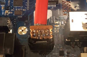
- CN1700 has now a JST 2.5mm connector in place. Although not the right size, with slight bending of the legs I successfully soldered one into place.
- I don't have the skills or hardware to solder in the 0402 surface mount capacitors so I came up with an alternative solution for adding the capacitors. It doesn't look as neat but it does work.
- Solder in wire jumpers on the motherboard in place of the capacitors.
- Use a small breadboard on which you can mount some more manageable sized capacitors.
- Cut the plug off a SATA data cable and strip off the 'rubbery' part to expose the connecting pins.
- I bent the ground pins down and data pins sideways to connect to the 2x4 breadboard. Solder them in place.
- Strip the ends of the wires on the SATA data cable. Solder the data wires to the breadboard on the other end of the breadboard and the ground wires to the ground plane on the other side of the breadboard.
- Solder in the capacitors between the data wires. I guess it is possible to use any size that will fit. I got mine from damaged ide to sata adapter
- hot glue and heat shrink was added after making sure that connection works fine.
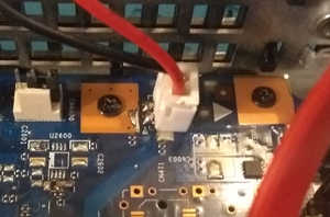
I've attached some pics of the monstrosity
Here you can see the finished result. The 4x2 breadboard has been cut down from a larger piece and has
a ground plane on the reverse side. The 'bent down' earth pins on the plug have been soldered to that with
the data pins being soldered to the top of the board. A similar approach is taken with the cable edge of the
board, with the four capacitors added between the plug and the cable.
The oversized plug soldered in the CN1700 location.
[David] You could also just cut the data cable a suitable distance from the plug and splice the board/capacitors in there rather than fight with the plug. At the same time you can take the opportunity to shorten the data cable so that the length is just right for where you've decided to mount the SSD.