The device label carries the information:
| MODEL NO | : | N06D |
| PART NO | : | 00061H |
| SID | : | 646A9X7LCF2 |
| PROD ID | : | ASSY,CHAS,4GBF/2GBR,TPM,3030LT |
The basic specs for my 3030 LT are:
Processor Type
SpeedIntel Celeron N2807 Dual Core
1.6GHzMemory Flash
RAM4GB (eMMC soldered down)
2GB (soldered down)Video Chip
Max resolutionIntel HD Graphics
2560 x 1600 32-bit colour (Display Port)
1920 x 1200 32 bit colour (DVI via adaptor)
2560 x 1600 32-bit colour (VGA via adaptor)Ports Video
Network
USB
Serial
Parallel
PS/22 x Display Port
10/100/1000
3 x USB2.0
1 x USB3.1
0
0
0Power Plug
Off
Idle
RunningCoax 5.5mm/2.1mm
0W
2.5W
3WDimensions H x W x D (mm) 187 x 29 x 117 (without stand)
198 x 69 x 117 (with stand)
The 3030 LT runs Linux and is fitted with 4GB of flash and 2GB of DDR3 RAM.
My 3030 LT came with a 12V 2.5A Chicony PSU. Despite what is mentioned in some data sheets the back panel is clearly marked +12V by the power socket. (Subsequent models may use a 19V supply). The connector is a standard coax plug: 5.5mm/2.1mm.
The power consumption is low (<6W) so you do not need a particularly highly rated power supply. Out of interest I did try out a (ex router?) 9V/2A 'Wall Wart' style power unit with the 3290. The 3290 apparently ran without any problems.
If you need to do this is it is fairly straightforward. You need to remove the foot (if fitted) which is a push fit. Then remove the three screws on the back panel. You then need to gently lever off the side panel that covers the top of the PCB. Start at the two back corners as the internal metalwork on the front edge actually slides under a lip just behind the front panel. When you get it clear at the back you need to move the panel towards the rear to clear this lip. On re-assembly you need to remember that you need to locate the front edge under this lip before pushing the side panel back on.
For those to whom it matters here is some detail from Linux's /proc/cpuinfo. (Dual Core Processor)
vendor_id : GenuineIntel cpu family : 6 model : 55 model name : Intel(R) Celeron(R) CPU N2807 @ 1.58GHz stepping : 8 flags : fpu vme de pse tsc msr pae mce cx8 apic sep mtrr pge mca cmov pat pse36 clflush dts acpi mmx fxsr sse sse2 ss ht tm pbe nx rdtscp lm constant_tsc arch_perfmon pebs bts xtopology tsc_reliable nonstop_tsc cpuid aperfmperf tsc_known_freq pni pclmulqdq dtes64 monitor ds_cpl vmx est tm2 ssse3 cx16 xtpr pdcm sse4_1 sse4_2 movbe popcnt tsc_deadline_timer rdrand lahf_lm 3dnowprefetch epb tpr_shadow vnmi flexpriority ept vpid tsc_adjust smep erms dtherm ida arat
00:00.0 Host bridge: Intel Corporation Atom Processor Z36xxx/Z37xxx Series SoC Transaction Register (rev 0e)
00:02.0 VGA compatible controller: Intel Corporation Atom Processor Z36xxx/Z37xxx Series Graphics & Display (rev 0e)
00:17.0 SD Host controller: Intel Corporation Atom Processor E3800 Series eMMC 4.5 Controller (rev 0e)
00:1a.0 Encryption controller: Intel Corporation Atom Processor Z36xxx/Z37xxx Series Trusted Execution Engine (rev 0e)
00:1b.0 Audio device: Intel Corporation Atom Processor Z36xxx/Z37xxx Series High Definition Audio Controller (rev 0e)
00:1c.0 PCI bridge: Intel Corporation Atom Processor E3800 Series PCI Express Root Port 1 (rev 0e)
00:1c.1 PCI bridge: Intel Corporation Atom Processor E3800 Series PCI Express Root Port 2 (rev 0e)
00:1c.2 PCI bridge: Intel Corporation Atom Processor E3800 Series PCI Express Root Port 3 (rev 0e)
00:1c.3 PCI bridge: Intel Corporation Atom Processor E3800 Series PCI Express Root Port 4 (rev 0e)
00:1d.0 USB controller: Intel Corporation Atom Processor Z36xxx/Z37xxx Series USB EHCI (rev 0e)
00:1f.0 ISA bridge: Intel Corporation Atom Processor Z36xxx/Z37xxx Series Power Control Unit (rev 0e)
00:1f.3 SMBus: Intel Corporation Atom Processor E3800 Series SMBus Controller (rev 0e)
01:00.0 Ethernet controller: Realtek Semiconductor Co., Ltd. RTL8111/8168/8411 PCI Express Gigabit Ethernet Controller (rev 06)
Expansion of the 3030 LT is limited, there is little room inside the housing and the Flash and RAM memory are soldered to the board. Click on the photo right for a larger version.
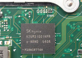
Flash: The flash is a 4GB eMMC chip soldered to the bottom of the board.
RAM: The RAM is a 2GB DDR3 L RAM with a 1.333 MT/s data transfer rate. It is soldered to the top of the board just under the edge of the heatsink.
M.2: There is a M.2 socket for a wireless module. The PCB is clearly marked WLAN by it and there are two mounting holes on the rear panel for the antenna. As you can see no Wireless card was fitted to my example.
mSATA: There is an unpopulated mSATA area on the PCB. This is usable if you add the socket and the four missing (very small) surface mount capacitors in the data lines. However you have to switch to the 3290 BIOS if you want it to be found. This has the side effect making the eMMC flash vanish as there is no support for it in the N03D BIOS.
USB: There is a single USB 2.0 port on the rear and three ports on the front panel, the top one of which is to the 3.1 USB standard.
 The onboard Flash Chip.
 The onboard RAM tucked under the edge of the heatsink.
 The 'Clear CMOS' push-button in the corner of the PCB.
 The 'BIOS' push-button on the PCB. I have no idea what this does.
A few observations on the earlier board compared to the this later LT version.
